PRECURSOR
MICROSATELLITE

PROJECT DESCRIPTION
The PRECURSOR Microsatellite is a private non-profit
mission. Private people, research institutes and universities support this project.
The PRECURSOR is built with both commercial and open source resources. This
means hardware as well as software.
The mission of the PRECURSOR belongs to IOD/IOV (In Orbit Demonstration/In
Orbit Validation) activities.

LANDSPACE
Land
Space Technology Corporation Ltd. is a Chinese private aerospace enterprise
engaged in the R&D and operations of launch vehicles. Focusing on small and
medium scale commercial aerospace application market, Land Space is devoted to
the development of Liquid-fuel Rocket Engines (LREs) and low-cost commercial
launch vehicles with independent intellectual property rights. Land Space could
complete the system and unit design, manufacture, test and delivery with
highly-integrated design and innovation capability by a first-class technical
team, to provide the global market with standardized launch service solutions.
Land
Space always considers the technical innovation and market-orientation as the
core development task, and is confident to become a beneficial supplement of
China Aerospace, to continuously boost its future development.
LAUNCH VEHICLE
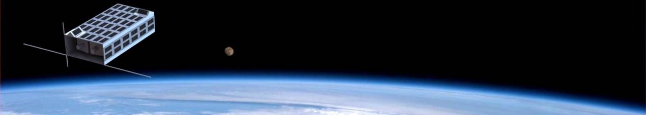
The PRECURSOR Microsatellite will be launched from
China on December 2024 from the Jiuquan Satellite
Launch Center (JSLC) in China. The launch vehicle
operator is the Chinese Start-Up LandSpace and the
PRECURSOR flight will be the second flight of the ZQ-2 launch vehicle. The ZQ-2
is a two-stage liquid propellant (LOX+LCH4) launch vehicle with a capability of
1.8 tonnes payload into 500 km SSO (Sun-Synchronous Orbit).

Figure 1: ZQ-2 Launcher
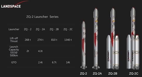
Figure 2: ZQ-2 Launcher Series

Figure 3: Mission Profile
Table
3: typical mission profile (ZQ-2 Block 1, 500km SSO)
|
Event |
Time (s) |
Altitude (km) |
Velocity (m/s) |
|
1st stage Ignition & Lift-off |
0 |
0 |
0 |
|
1st stage cut-off (MECO) |
151 |
69 |
1,960 |
|
2nd stage ignition |
155 |
74 |
1,928 |
|
Fairing separation |
212 |
140 |
2,733 |
|
2nd stage main engine cut-off (SECO) |
290 |
239 |
4,896 |
|
2nd stage Vernier cut-off (VECO) |
760 |
500 |
7,613 |
|
Payload deployment |
770 |
500 |
7,617 |
Table
4: Typical Separation Accuracy
|
Parameter |
Angle |
Rate |
|
Roll deviation |
≤0.7° |
≤0.3°/s |
|
Pitch deviation |
≤1.5° |
≤1.0°/S |
|
Yaw deviation |
≤1.5° |
≤1.0°/s |
Table
5: Injection Accuracy
|
Symbol |
Parameters |
Deviation |
|
△a |
Semi major Axis |
±5km |
|
△e |
≤1.5° |
0.003 |
|
△i |
≤1.5° |
±0.08 |
SATELLITE DESCRIPTION
The PRECURSOR Microsatellite doesn’t follow any kind
of standards like the CubeSat standard. The CubeSat standard has limitations and
for the mission objectives a customized solution is the best option. The
PRECURSOR satellite has the sizes 15x30x60 cm3. The weight is
approximately 17kg. The main experiment is a new generation propulsion system
for Orbital Plane Change (inclination) and/or Orbital Altitude Change and uses
green propellant. The PRECURSOR Microsatellite will validate several
technologies. The satellite is designed using Commercial electronics and
materials, Open Source Hardware and Open Source Software. This strategy allow
the quick implementation of this new satellite platform. Other experiments inside the PRECURSOR is a
multi-band GNSS receiver with a newly High-Performance GNSS Antenna for small
satellites.
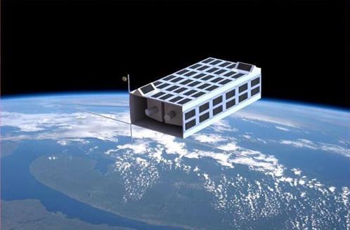
Figure 4: Representation PRECURSOR Satellite in
orbit
ON-BOARD COMPUTER (OBC)
The OBC is based on the EFR32FG12 processor from
Silicon Labs. The OBC has four processors, one is the main and the other one
the backup. The processor was irradiated with Gamma rays and it was
demonstrated that this processor can be used in LEO orbit for several years.
Following are the most important characteristics of the OBC:
- Four ARM Cortex M4 with 40MHz.
- Operating supply voltage
between 3.7 – 4.0 V
- Internal FLASH memory of 1MB
- RAM size of 256 kB
- Interfaces available are I2C,
SPI and UART
- 46 GPIOs
- Operating temperature in a
range between +20°C to +85°C
- Data Bus Width of 32 bit
- ADC with a resolution of 12 bit
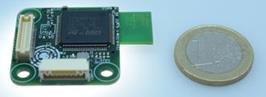
Figure 5: Small size computer
OPERATING SYSTEM
The PRECURSOR Microsatellite uses RODOS (Realtime Onboard Dependable Operating
System) as operating system.
RODOS was developed at the German Space Agency (DLR) and is a derivate from the
BOSS operation system, which is used in the micro-satellite program DLR's.
Satellites using this operation system are BIRD and TET-1 and BiROS. RODOS is ideal for Telemetry and Telecommands
tasks. It is light to migrate to other systems.
RODOS is an open source software and is implemented in C++ and has also
following features:
- object-oriented C++ interfaces,
- ultra-fast booting
- real time priority controlled
pre-emptive multithreading,
- time management (as a central
point),
- thread safe communication and
synchronisation,
- event propagation

Figure 6: RODOS OS Logo
POWER MODULE
The power module consists of a set of solar cells,
Lithium batteries and the electronic to regulate and distribute the power in
the system.
The Power Conditioning Distribution Unit (PCDU)
distributes it internally to the energy consumers or to the batteries.
The Maximum Power Tracking (MPPT) charge controller
allow to maximize the energy extraction generated by the solar panels.
Solar Cells
The solar cells are commercial and has the size of 125x41,6
mm. Each cell is equipped with 12.5µm Ag interconnector welded to the solar
cell in-contact. The solar cell is covered with 0,7 mm thick Borosilicate glass
with the size of 41,6x125 mm.15mm bonded by use of silicone adhesive DC93500.
The cells have an efficiency of around 23%, with a voltage of 0,5V and 1,2W per
cell.

Figure
7: PRECURSOR Solar Cells
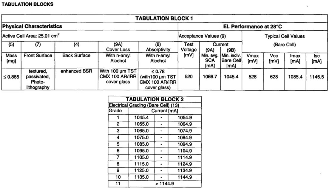
Figure
8: Solar Cells Characteristics
Batteries
In order to increase the lifetime of the batteries a properly reload cycles is
essential. The power electronic will configure automatically the best reload cycles
and power consumption, monitoring constantly the status level of the batteries.
Each cell has following characteristics:
- Nominal voltage: 3.6 V/cell
- Nominal capacity: 1600 mAh /cell
- Operating temperature: -25°C to
55°C
The charge and discharge process will be controlled
with a charge controller IC, which is equipped with a MTTP (Maximum Power Point
Tracking) control unit.
The power module has a power capacity of 10Ah (11V).

Figure
9: Lithium Ion Cell High Energy (Source EAS)
COMMUNICATION MODULE
It consists in a modem and transceivers which converts
the digital data in an analogue signal. The data to be transmitted will be provided
by the OBC, which administrates the data distribution and encapsulation. The
standard CCSDS will be used for encapsulation purposes. The communication
module transmits and receives in VHF, UHF, L-Band and S-band.
Following transceiver will be used:
VHF/UHF Transceiver
The selected transceiver will be tested in order to see the radiation
robustness. Thermal-Vacuum and Outgassing tests will be also included.
Characteristics of the transceiver:
- Data rate: 256 kbps
- Power transmission:0,1-2W
Uplink Frequencies
·
435.0125-435.0375
·
436.17875-436.19125
Downlink Frequencies
·
145.9625-145.9875
·
144.01-144.02
L-Band
Receiver
Uplink Frequencies
·
1261.25-1261.75
·
1260.11875-1260.13125
S-Band
Transmitter
Having a camera as payload is important to transfer data
in a higher data rate as is possible by the UHF transceivers. For this reason
for the remote sensing experiment S-Band transceiver is recommended. Following
modules characteristics are considered:
- Data rate: 1,06 Mbit/s
- Power transmission: 2 W
- Error correction: 32 bits CRC
Downlink Frequencies
·
2400.6-2401.1
·
2400.84375-2400.85625
ITU LICENSE
You can find the ITU license under following link:
![]()
THERMAL CONTROL
The thermal behaviour of some sensible components like
the batteries and solar cells will be monitored by using temperature sensors.
The thermal sensors and the heaters will be controlled by the OBC.
Temperature Sensors
The temperature sensor PT1000 will be used in the PRECURSOR. Such sensor is
commonly used as thermometer in microcontrollers but also often in satellites
Heaters.
The Heaters will be also used specially for batteries conditioning. The
selected heaters have high quality, low power consumption and small sizes. In
that way the temperature can be regulated in a range for save operation of
sensible electronic, typically between -20°C and +60°C.
Heat Sink
For thermal control one side (30x60 cm2) of the satellite structure will point
constantly to the Earth. This side will be used as heat sink and it will
dissipate the excess warmth.
ATTITUDE SYSTEM
The Attitude subsystem will consist of two different
parts. The first one will be a sensor set of Sun sensors, Magnetometers,
Accelerometers and Gyroscopes for orbit determination.
The second part will be built with a set of actuators, consisting of magnetic
coils and micro-reaction wheels.
With the mentioned configuration the Attitude system fulfils a required
accuracy of +/- 5°. Further, the Attitude System will have its own
microcontroller to manage the complexity of the required calculations for
attitude control.
The attitude system will have following characteristics:
- Size: 9,5x9,5x10cm
- Mass:1000g
- Power consumption: 0,5-1,8W
- Attitude Knowledge: ±5°
- Pointing accuracy: ±6°
- Sensors: Accelerometers
(3-axis); Gyroscope (3-axis); Magnetometer (3-axis)
- Actuators: 3 reactions wheels
(torque 0,087mNm / 1,5mNms)
Figure
10: Multi-sensor Board
PAYLOAD
In the PRECURSOR mission many technologies will be
tested but following main experiments are the principal payloads:
Payload
Computer
The payload
computer is based on two Raspberry Pi 4. One is the main computer and the other
is the redundant computer. Both RPi-4 have the same software and have the
following functions:
·
Communication
with the on-board computer.
·
SDR Radio
Control (Multifunction)
·
U-Blox GNSS receiver
·
S-band transmitter
·
L-band
receiver
·
USB camera
control
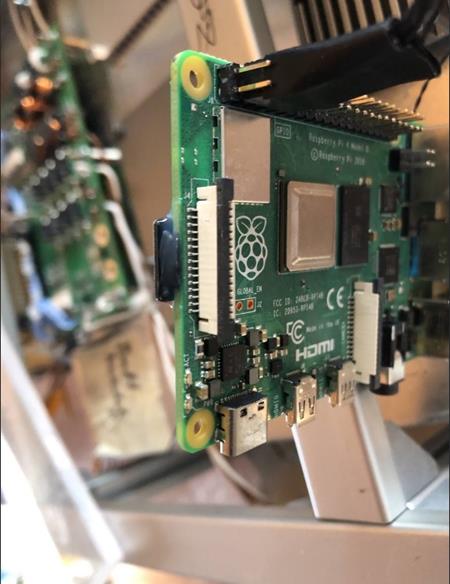
Figure 11: Raspberry Pi 4 installed
in PRECURSOR
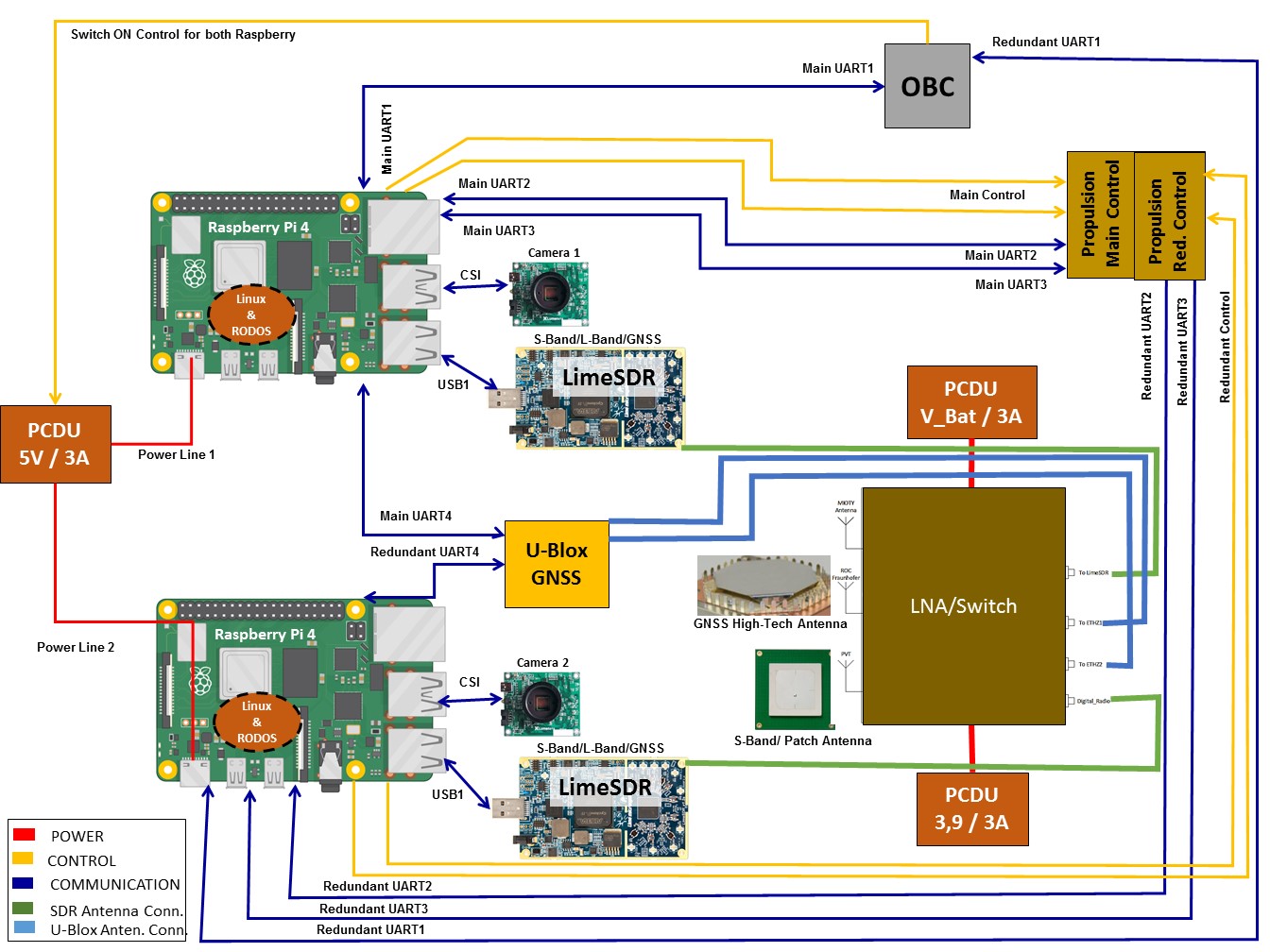
Figure 12: Payload Block Diagram
Propulsion
System
The main payload consist in a new generation propulsion
system. This propulsion system was designed for:
- Orbital Plane Change
(inclination)
- Orbital Altitude Change
This is the first time that such engine will be tested
in space. The propulsion system uses green fuel and has a maximal thrust of
2.5mN. The fuel volume is 1700 ml.
The thrust engine is based on the Magnetic Field
Oscillating Amplified Thruster (MOA). This thruster is able to accelerated
charged gases to extremely high velocities generating a high energetic plasma
jet.
During the mission several manoeuvres will be achieved
with the propulsion system. The exact positions during the manoeuvres will be
tracked and registered on-board with the GNSS receivers and the raw data will
be processed on the ground.
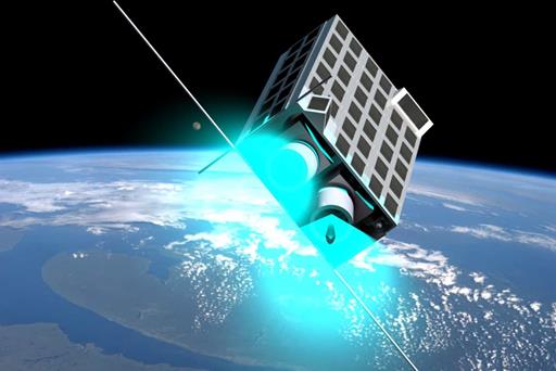
Figure 11: PRECURSOR Thrusters activation
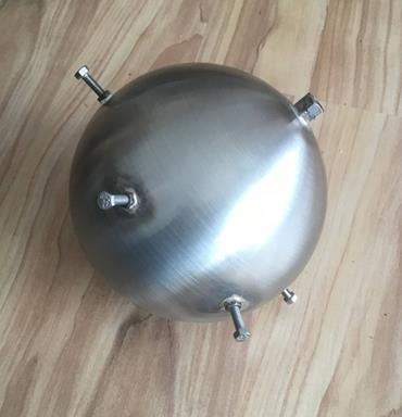
Figure 12: Fuel tanks
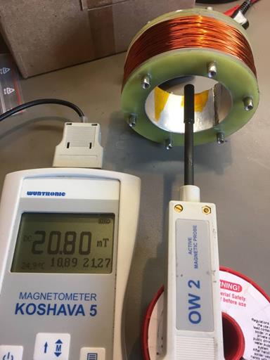
Figure 13: Thruster magnetic field intensity
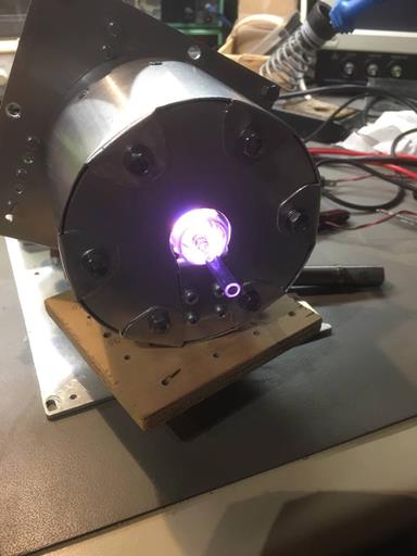
Figure 14: Plasma Test
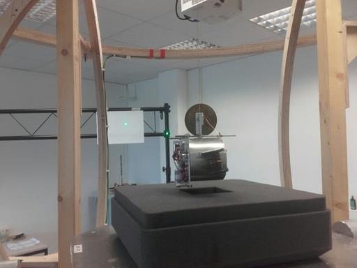
Figure 15: Magnetic Momentum Test
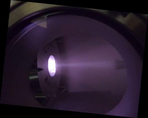
Figure 16: Thrust Test in the TV Chamber
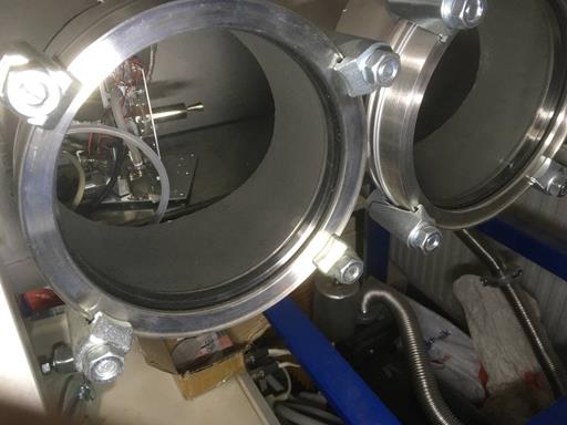
Figure 17: TV Chamber and Test Setup
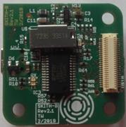
GNSS
Receiver 1
The GNSS payload consists of a GNSS receiver board
equipped with four u-blox ZED-F9P receivers,
connected to two GNSS antennas located on the outer surface of the satellite.
It is contributing to the mission objectives by determining the satellite
position, velocity and time (PVT). After downloading the data to ground, in
post-processing the GNSS code and carrier phase measurements are preprocessed and a reduced-dynamic orbit is fit into the
kinematic positions for orbit analysis. This will allow for the detection of
changes in the orbital elements and thus, to assess the performance of the
propulsion system onboard the PRECURSOR satellite.
After the primary mission goal has been achieved, the GNSS payload board will
be used for testing the radio occultation capability of the GNSS receiver.
Characteristics of the receiver board
•
Size: 96 x 90 x 22 mm
•
Mass: 250 g
•
Connectors: SMA, Gecko 10 pin
For validation of the GNSS-based PVT solution, a
reflector array is installed on the satellite. It consists of three corner
cubes glued in a custom made aluminum structure.
Mounted on the nadir-looking face of the satellite, it allows
satellite-tracking from a global network of laser ranging stations and
therefore, enables precise orbit determination on the sub-dm
level during dedicated measurement campaigns.
Team ETH:
Gregor Moeller, Flavio Sonnenberg, Alexander Wolf, Markus Rothacher
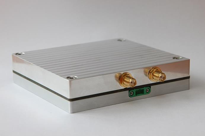
Figure 18: Case of the High-Precision GNSS Receiver Module
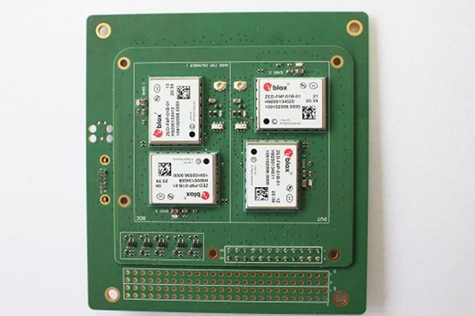
Figure 19: GNSS Receiver Board with 4 u-blox
ZED-F9P Receivers
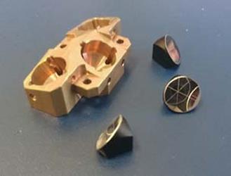
Figure 20: Laser Retro-Reflector
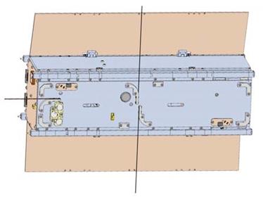
Figure 21: Retro-Reflector Mounting
GNSS
Receiver 2
A LimeSDR receiver
A LimeSDR receiver will be
used as GNSS receiver. The application software is based on open-source code.
The receivers have a high precision clock with following characteristics:
- Frequency 10.000000MHz
- Stability 0.1 - 0.5 ppm
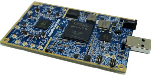
Figure 22: LimeSDR Radio
Receiver (Source: limemicro.com)
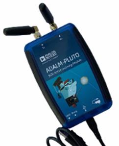
A second SDR
will be used as backup system. In this case we will use an Adalm-Pluto
and it will be connected to a Raspberry Pi 4 too.
GNSS Antenna
The GNSS antenna is a new generation antenna designed
for small satellites. The antenna has following characteristics:
- Size: 10x8.3x1 cm
- Mass: 20g
- Passband: 1160 - 1300 MHz and
1525 - 1610 MHz
- Polarization: RHCP
- Passive zenith gain: L1, E1, G1
>1.5 dBic and L5, L2, E6 >0 dBic
- Passive horizon gain: >-7 dBic
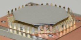
Figure 23: PRECURSOR GNSS Antenna
RADIATION
SENSORS
In this
experiment commercial transistors will be used as radiation sensors. The
selected transistors are manufactured with standard low-power enhancement mode
lateral pMOS technology. Designing a low-cost
hand-held measurement system using this pMOS as the
sensor would have a clear advantage due to the lower cost incurred by a
standard technological process.
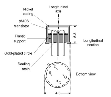
Figure 24: Transistor
3N163 as radiation sensor
STRUCTURE
To protect the electronic inside against radiation a
robust structure helps to reduce the radiation dose and extend the lifetime of
the electronic parts.
The design of the structure is customized and compliant with mission
requirements, where following types of duralumin will be used for the walls:
5052 H32 and 6061 T6. The solar cells will be attached to the structure sides.
Small pieces will be printed and with PEEK material manufactured.
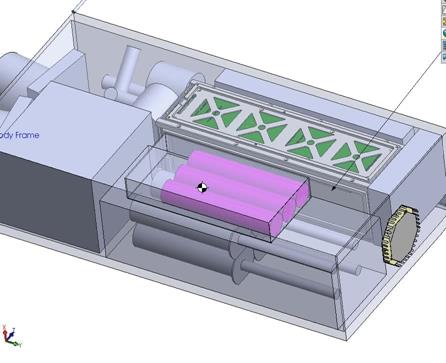
Figure 25: PRECURSOR Structure
PAYLOAD CONTAINER DEPLOYER
For the satellite a customized deployer
is designed. The deployer will be manufactured with
Duralumin 7075 T6, and 3D printed parts.
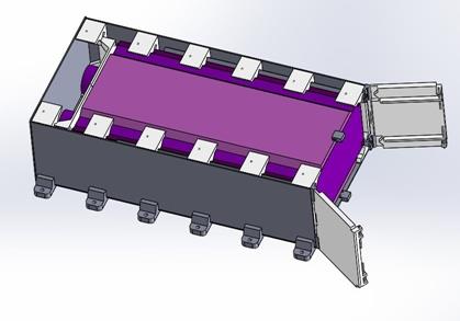
Figure 26: PRECURSOR Deployer
ENVIRONMENTAL TESTS
The payload has to absolve an acceptance
qualification. In this process will be proofed that the payload can withstand
the flight on the ZQ-2 without damaging other payloads.
Following environmental tests will be achieved prior
the launch:
- Vibration Sinusoidal
- Vibration Random
- Shock Test
- Outgassing
- Thermal Vacuum
Some tests will be achieved at System level or at
module level.
·
VIBRATION
The major stress during the flight will be generated from the launch
vehicle vibrations. It must be guaranteed that the payload will not be
destroyed during the launch.
o
SINE VIBRATION
The
table 6 lists the experimental conditions for low frequencies sine vibration
from
5Hz
to 100Hz, which are used to simulate the transient and stationary random
vibration of a launcher.
Table
6: Low Frequency Sine Vibration Scan Test Condition
|
Position |
Frequency Range(Hz) |
Acceptance Level |
Identification
Level |
|
Payload
Bracket |
5~10 |
2mm |
3mm |
|
10~100 |
0.8g |
1.2g |
|
|
Scanning
Rate R |
4.0Oct/min |
2.0Oct/min |
|
o
RANDOM VIBRATION
The
table 7 gives the test conditions of random vibration at high frequencies
ranging from 20 Hz to 2000 Hz, which can be used to simulate the transient and
stable random vibration of a rocket.
Table
7: Payload Interface Random Vibration Levels
|
Position |
Frequency Range (Hz) |
Acceptance Level |
Identification Level |
||||
|
Power
Spectral Density (g2/Hz) |
Duration
of
Test Runs (min) |
Total
Mean Square Root(g) |
Power
Spectral Density (g2/Hz) |
Duration of
Test Runs (min) |
Total Mean Square Root (g) |
||
|
Payload
Bracket |
20~150 |
3dB/Oct |
1 |
6.94 |
3dB/Oct |
2 |
10.41 |
|
150~800 |
0.04 |
0.09 |
|||||
|
800~2000 |
-6dB/Oct |
-6dB/Oct |
|||||
·
SCHOCK
The
impact experiment condition (shock response spectrum Q=10) is shown as the
table 8. The response acceleration time history in three vertical directions at
the bottom of the specimen must be measured during the test.
Table
8: Shock Response Spectrum (Q=10)
|
Position |
Frequency Range(Hz) |
Acceptance Level |
Identification
Level |
|
Satellite |
50~1000 |
9dB/oct |
9dB/oct |
|
1000~8000 |
3000g |
4500g |
|
|
Semi-sine
vibration test: peak value of the accelerated velocity is 200g;PW is 6ms with X
direction; Repeat the test 3 times for each direction. |
|||
·
ACOUSTIC
Acoustic
condition is detail in table 9.
Table
9: Payload Acoustic Environment
|
1/3 band Central frequency
(Hz) |
1/3Sound Pressure
Level / dB in band Width |
|
Inside the Fairing |
|
|
25 |
111 |
|
31.5 |
113 |
|
40 |
115 |
|
50 |
120 |
|
63 |
125 |
|
80 |
127 |
|
100 |
129 |
|
125 |
130 |
|
160 |
131 |
|
200 |
131 |
|
250 |
131 |
|
315 |
132 |
|
400 |
132 |
|
500 |
132 |
|
630 |
131 |
|
800 |
131 |
|
1000 |
129 |
|
1250 |
126 |
|
1600 |
123 |
|
2000 |
121 |
|
2500 |
120 |
|
3150 |
119 |
|
4000 |
117 |
|
5000 |
115 |
|
6300 |
114 |
|
8000 |
112 |
|
SPL |
142 |
·
EMC
The
Electromagnetic radiation for the radio equipment on the launch vehicle and
also the launch site cannot exceed the requirement shown in the table10.
Table
10: EM radiation of the rocket and launch site
|
Frequency(MHz) |
Intensity(dBμV/m) |
|
0.01~0.05 |
80 |
|
0.05~3 |
90 |
|
3~30 |
70 |
|
30~550 |
65 |
|
550~750 |
103 |
|
750~2200 |
90 |
|
2200~2300 |
138 |
|
2300~1000 |
90 |
|
10000~ |
90 |
GROUND SEGMENT
The ground segment consists in radio-amateur ground
stations, which allow the effective operation of the mission. For commanding
two stations will be used. For downlink the telemetry if open and free for the
radio-amateur community. For the communication issues the project has the
support from AMSAT-DL.
Principal capabilities and features of the ground segment:
- All stations have the similar
hardware and software configuration
- Remote or autonomous (without
staff) control
- Collected data can be
transferred between stations
- Uplink with two station
possible
- Downlink for all support
stations
- The duration of one pass takes
around 10 min
- Number of contacts in average
per day and per station is 4 in average
- Data download in average of 703
KB (UHF) per contact
The core components of the PRECURSOR ground station
are:
- Transceiver ICOM IC-9100 (VHF
and UHF)
- Power supply for the
transceiver PS-125.
- Two pre amplifiers (one for
VHF, other for UHF)
- Antenna rotor Big-RAS
- Two Yagi antennas, one for VHF
(2 m), other for UHF (70 cm)
- Cables and connectors
- Personal computers with network
adapter
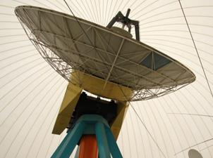
Figure 27: AMSAT-DL 20m antenna in Bochum
MISSION OPERATIONS
A group of 4 Operators (licenced radio amateurs) will
be available for this project.
The mission operations team will manage the schedule of the satellite contacts,
depending on the payload activities.
The mission operation prepared is based on the ESA standards for flight control
organisation and will have the following phases:
Pre-Launch phase
Before satellite will be launched
the team will be trained for all phases of the mission using a duplicate of the
most important satellite parts. This twilling system will build a simulator
helping to restage all the cases of the mission to operate the satellite. The
team will be also trained to manage all routine activities and emergency cases.
In this phase all necessary procedures and documents will be written and
validated.
LEOP phase
During this
critical phase the satellite will be in contact with all possible ground
stations in order to initialise all the subsystems. Test transmissions with the
ground stations and each function of the satellite will be checked. All the
subsystems will be configured for the routine operation. In this phase the
operations team will work with the bus only but not with the payloads. The
operation service of 24 hours begins on shifts. The organization of the flight
control team will be redundant following the ESOC typical organisation for a
LEOP.
Commissioning phase
In
this phase the operations team will work with the payloads. The payloads will
be switched, checked and configured. After that the calibration of the
instruments will be achieved. During this phase is necessary to be in contact
with the instruments responsible in case of malfunctions.
Routine phase
During this phase the team will
keep the 24 hours shift work but the activities will be reduced and for any
anomaly an On-call service will be available. The satellite will keep the
nominal mode and the instruments (payload) will collect science data. In the
scheduled contacts the science data will be down-linked, stored and forwarded.
Recovery
In case of an emergency situation and the satellite is
not able to go back to the nominal mode due to several errors the team has to
execute emergency procedures and have to prepare the commands to recover the
spacecraft.
For the PRECURSOR mission operations following
activities are planned:
- Daily downlink of the
housekeeping telemetry
- Daily downlink of the science
data
- Manoeuvres with the propulsion
system
- Experimental measurements with
the GNSS receivers
- Downlink of the GNSS
measurements raw data
- Post-processing of the raw data
TEAM
Jaime 
Jaime Estela is an electronic engineer born in
Lima-Peru. He worked at the German Space Operations Center
of DLR in Oberpfaffenhofen for 11 years. In this
period he gathered experience in satellite operations and systems engineering
and supported several LEO orbit satellite missions like Terrasar-X,
Tandem-X, Prisma A & B, Grace 1 & 2, CHAMP,
BIRD, TET and was also involved, as Ground Segment Engineer, in the ESA project
Columbus, space laboratory onboard the ISS,.
Furthermore
he has supported CubeSat projects developed by Universities. He supported the
project QB-50, an international constellation of 50 CubeSats
which will study the higher ionosphere in a low Earth orbit and during its
re-entry as suborbital research platform.
Jaime is a
supporter of the NewSpace initiative and contributes
to this space movement actively with new concepts, ideas, products and
services.
Alex 
Dr. Alexander Popugaev received the M.S. degree (with
honours) in radio engineering from the Vladimir State University, Russia, in
2004, and the Dr.-Ing. (Ph.D.) degree (summa cum
laude) from the Technical University of Ilmenau,
Germany, in 2013.
Since 2004,
he has been with the Fraunhofer Institute for
Integrated Circuits IIS, Germany.
During his
over 15 years long tenure at the RF and Microwave Design Department, later RF
and SatCom Systems Department, Dr.
Popugaev worked his way up from Research Associate to
Chief Scientist.
Due to his
successful long-time R&D activities in the field of customer-specific GNSS
antennas, Dr. Popugaev
moved in 2020 into the Satellite Based Positioning Systems Department. His
current position is Business Development Manager for GNSS Antennas.
Dr. Popugaev has authored and
co-authored several scientific papers and book chapters and has received
several patents.
Tobias 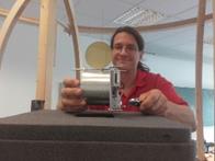
Tobias
Bartusch is an electrical engineer since 2000 (FH Augsburg) and physicist
(Univ. Augsburg) since 2006. He gained theoretical and practical experience in
many space projects in different companies since 2006 (neutralizers and
RF-multi staged magneto-plasma thrusters, boxes / modules for various
customers, atomic clocks, timing systems and analog
space design, AIT and Systems Engineering). In addition, he has developed high
vacuum systems (tubes, electron emitters, plasma sources and measurement equipment)
and vacuum chambers. He is experienced in the development of vacuum COTS
equipment and space materials / high vacuum materials such as coatings for
thermal radiators, AtOx resist, PTFE, and other. In
the Precursor project, he is the responsible engineer for AIT, thermal design,
deployment box, solar panels, charger, electrical thruster, some power
converters, parts of the antenna integration and test. He is also a radio
amateur (DH2MBT) and member of the DARC and AMSAT-DL. The satellite will be
integrated in his workshop and laboratory which has the capability to perform
all necessary steps.
Miguel 
Miguel Ángel Carvajal Rodríguez: Tenured
Professor of the Department of Electronics and Computer Technology, CITIC-UGR,
IMUDS-UGR, University of Granada, Granada, SPAIN
Alberto 
Alberto José
Palma López: Full Professor of the Department of
Electronics and Computer Technology, CITIC-UGR, University of Granada, Granada,
SPAIN
Gregor 
Gregor
Moeller is a senior scientist and lecturer at the Institute of Geodesy and
Photogrammetry at ETH Zürich with focus on high-precision GNSS, nanosatellite
orbit determination and atmospheric remote sensing.
Andrés 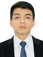
Electrical
Mechanical Engineer from the National University of Engineering of Peru, with
experience in development of space projects at undergraduate level in events
held by CNES FRANCE: C'SPACE 2019 with pico
satellites for meteorological applications and in C'SPACE 2022 with
experimental rockets for tropospheric missions. He participated in the development
of a mini autonomous vehicle for ground reconnaissance missions at the ARLISS
event held by the NATIONAL ASSOCIATION OF ROCKETRY USA.
In the
Precursor mission, he performed the modal analysis and thermal simulation of
the satellite structure.
PARTNERS


![]()
SPONSORS
![]() Bartusch
Plasma and Vacuum
Bartusch
Plasma and Vacuum 